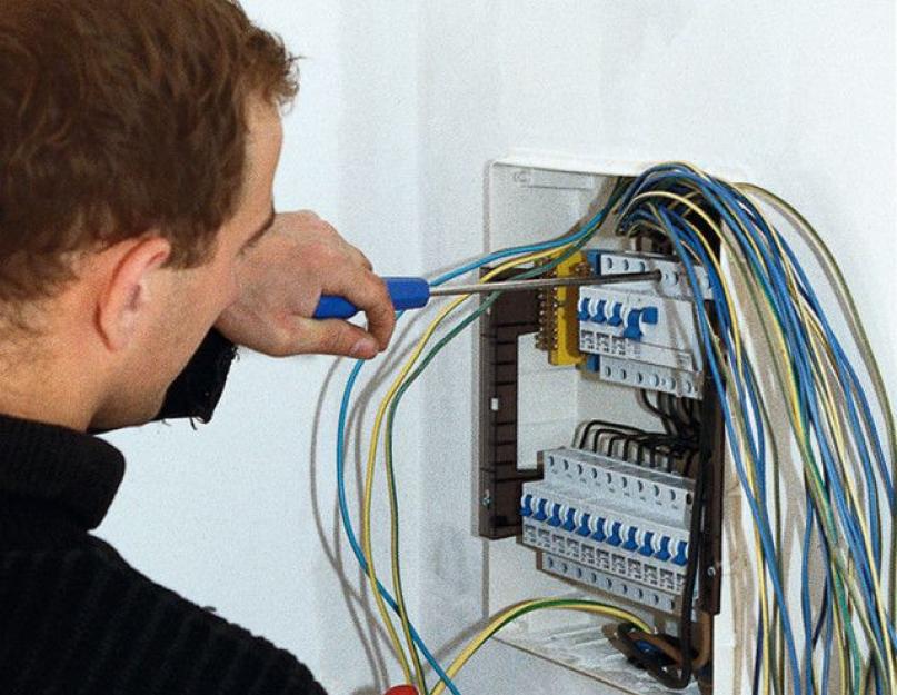
The comfort of life of a modern person directly depends on the availability of a reliable source of electrical energy. Almost everything is tied to it - lighting, cooking and food storage, space heating and water heating, air conditioning and ventilation, means of communication and access to information, dozens of other devices and devices, without which it is already difficult to imagine our existence.

Electricity suppliers in our time work stably, without serious and prolonged failures, and if the consumer pays for services on time, then he can count on full access to the available "benefits of civilization". But only energy supply companies guarantee the supply of voltage to the “watershed” - to the consumed energy. And then the area of responsibility of the landlord begins, and it is in his right to arrange all points of lighting and connection to the power grid in the optimal quantity, from his point of view, and in a convenient place for use. But how to approach this issue? Will the wiring be installed in the apartment with your own hands, or is it more expedient to use the services of electricians?

It is impossible to answer this question unambiguously. Much depends on preparedness, "savvy" landlord in the field of physics, electrical engineering. An important factor is the ability for long-term planning, since replacement work postings are implied for many years to come. And, in the end, the owner of the apartment must have a good set of skills in the field of general construction work - it will also not do without it.

In laying wiring - a considerable component of general construction work
The purpose of this publication is to give the owner of the apartment an idea of the scale of the measures for laying the home electrical network, about basic principles its planning, the correct distribution of loads, installation techniques and electrical fittings products, about other important nuances. There will be an opportunity to understand whether it is worth taking on such a volume of work on your own, or still invite qualified craftsmen. From the point of view of professionals, without practice and without electrical safety clearance, it is better not to do such work on your own, since there are a lot of nuances that simply cannot be described on the scale of one article - their knowledge comes with many years of experience. However, know basic principles wiring in an apartment will be useful to any owner - it will become possible to control the work of the masters (alas, there are rogues among them), and for the safe operation of housing, such an understanding of the issue will never be superfluous.
Anyone who received a new apartment in houses that were built and rented out according to the old principle - "turnkey" (although, as a rule, with not very high quality), knows how, often inconveniently, thoughtlessly, connection points to the power grid were placed there . Yes, everything corresponded to the old GOSTs, but the trouble is that these standards were written when the saturation of human life with a variety of electrical appliances differed significantly from current conditions.
As you acquire new appliances, you have to stretch extension cords around the apartment or even lay new lines, since some electrical installations clearly do not have enough rated power of old wires. stretching by by Lam cables are both a feeling of certain discomfort, and a clear minus for the interior design of the room.

Moreover, with insufficient connection points, many tenants who are poorly versed in electrical engineering make sometimes unimaginable connections using tees, even using them in several cascades. Alas, this is a direct road to the occurrence of a fire hazard in the apartment.
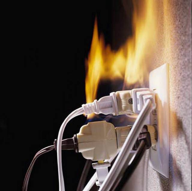
But this is already a direct path to big trouble.
And so, when sooner or later it's time to make a major overhaul in your apartment, the most reasonable step is to completely, from the entry point to the last outlet, replace both the wiring and the entire electrical fittings part by planning the installation of power connection points in the most convenient, rational and safe way.
There is another very important reason to ever completely change the cable part. The fact is that during the construction of high-rise buildings in the old days, for reasons of economy, internal wiring was in most cases made of aluminum wires. Aluminum seems to have good electrical conductivity characteristics, but now it is practically not used for these purposes, since its disadvantages far outweigh its advantages.
- First, the metal itself is very soft. It is easily deformed, pressed through when using contact screws, terminal washers, etc. - it is unlikely that it will be possible to make contact twice in one place - the wire will simply break in a thinned place. That is, repair work with aluminum wiring is extremely difficult. Soldering it is very difficult, and in the conditions of installing home wiring it will be extremely irrational to use this technology.
- However, aluminum is only ductile when it is, let's say, "fresh". This metal has an amazing property - the electrochemical processes that occur in it during the passage of current radically change the properties of the substance over time. After 15 ÷ 20 years of operation (and for wiring - this is a very short time) aluminum conductors become brittle. Sudden, almost causeless, are not excluded, which can be very difficult to find, and even more difficult to eliminate, since the wire can break even with careful attempts to make a new twist or bend it for a terminal connection.
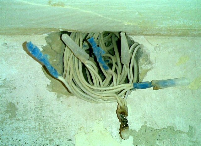
- Another striking property: it would seem that the metal is very resistant to corrosion, but it was not there! If even a small amount of water gets on the conductor, then under the action of electricity, electrocorrosion processes are inevitable. And, they may be invisible externally - in appearance, the whole conductor inside can be “corroded” so much that even a small one causes heating, sparking or failure. Sometimes any touch to such a wire leads to its breaking off.

Compare with the picture above - is there a difference?
In other words, if you are serious about electrical issues, then you should not hesitate to replace all the old aluminum wiring with on the reliable copper. Its electrical parameters are even higher, plasticity is good (but not excessive), and does not change either from time to time or from operation under heavy loads. The cost of copper wires is, of course, significantly higher, but the wiring in the apartment is done, as already mentioned, for decades to come, and saving on such issues is simply unreasonable. Along with the replacement, you can simultaneously solve all issues with the optimization of the placement of all elements of the home electrical network.
If the owner has purchased a new apartment, in a house that was commissioned on a do-it-yourself basis, then there is nothing to think about - you need to carefully plan the entire apartment electrical network, taking into account your vision of the location of electrical appliances and furniture in the rooms, and do the wiring literally in the first place - even before pouring floors, finishing walls and ceilings. Below in the text it will become clear why this is so.
A few more arguments in favor of not upgrading or repairing, but overhauling the old wiring.
1. In the old days, ground loops in residential buildings were not considered mandatory, and all intra-house networks were laid according to the TN-C system, when the working zero and ground were connected to a single wire (PEN) even at the electrical substation. The only advantage of this approach is ease of installation and minimal material consumption, since all sockets in the apartment were entangled with only two wires - zero and phase.

TN-C system - "the day before yesterday" of electrical engineering
During a reboot or a breakdown on the metal case of electrical appliances, a life-threatening voltage is very likely to appear. Moreover, this type of contact connection does not allow correct operation of residual current devices (RCD), some modern switching power supplies. Today, such a system is not used, in some places it is even prohibited by law, and it must be changed to one of the more advanced systems: TN-S or TN-C-S.
TN-S is more often used in private homes in which their own is organized. Although, in apartment buildings, grounding buses can be organized, connected by welding and passing from the external ground loop through all floors.

But still, the TN-С-S system is used more often in multi-storey residential buildings, in which deaf-earthed the neutral is divided into two conductors - a working zero and a ground loop, directly in the access switchboard.

In any of the last two cases, three contacts are already used for wiring - phase, zero and ground. You can immediately mention the color marking of these wires - one must comply with current standards.

Please note that the color of the phase wire may vary. But here, zero and grounding - have a mandatory color, so that it cannot be confused during electrical work.

By the way, several phase conductors can be enclosed in one cable. They will differ in color from each other, but at the same time, two conductors will still stand out with their obligatory color - “working zero” and “ground”.
A lot of modern electrical appliances are equipped with a three-prong plug. So, an important clarification needs to be made. When installing new sockets, the owners, of course, also try to install three-pin ones. However, if wiring has not yet been organized in your apartment according to the TN-S or TN-C-S schemes, then in no case should jumpers be made between the zero contact and the ground contact directly on the outlet.

If the life and health of your family and friends are not indifferent to you, never do such a “grounding”!!!
What can be done at the switchboard level - absolutely unacceptable right at the connection point. This will not only not give the desired effect, but also dramatically increase the level of danger. The likelihood of electric shock or a fire hazard with such a connection is huge! It is better not to have a connection to ground at all than to organize such a thing.
And even better - mount a new wiring in accordance with all the rules!
2. The second important argument is that the very principle of wiring, which was previously used in residential construction, is extremely imperfect. We are talking about the so-called "dosing" of the load. To understand - remember the old switchboards. An electric meter, two automatic machines (or fuses - plugs) - and that's it. Two wires went to the apartment, were lost somewhere in the thickness of the wall, and branches were made from them in contact boxes to each lighting point or outlet. In a word, as thin branches depart from the trunk of a tree, so layering was made from the main wires. Again: in terms of economy, this is beneficial, but in all other respects it does not stand up to criticism.
This system was literally teeming with twists on every branch, and any extra connection of wires is always a weak spot in the wiring. If it was necessary to de-energize one of the rooms, it was necessary to turn off the power in the entire apartment. Even a minor accident, an accidental short circuit on one of the branches, led to the shutdown of the entire apartment network. Well, if something serious happened (a cable breakage or burnout hidden in the wall), then the search for an emergency site and the repair work turned into a very difficult problem.

All this can be easily avoided if you organize a zoned wiring system - from the input point, that is, from the apartment switchboard, separate power lines are laid with the required wire section corresponding to the load, to each room, to each high power electrical appliance every a group of sockets or lighting. Yes, of course, you will need much more cable here, but on the other hand, the home electrical network will become convenient and safe to use, it will be easy to give in to the necessary upgrades or repairs.
The foundation of the basics - home electrical planning
So, the first step in any case is whether a major overhaul will be carried out. or wiring will be laid in a new apartment, there is always a drawing up of an apartment electrical network diagram. And it is best to do it yourself - no one but the owners can do it better.
Perhaps someone doubts their ability to carry out such planning. It's okay - there is no need to rush, we do everything sequentially, step by step. And you will see that it is not so difficult at all.
First, you need to prepare a plan for your apartment. There may be several options here. First, you can make a copy of the technical passport. Secondly, it should not be difficult for a real man to draw an approximate diagram (best of all, of course, on a scale) on a regular sheet of paper. Thirdly, if desired, you can find a typical project of the house in which the apartment is located. (Such a document may be in the DEZ, another operating or design organization. It is possible that the Internet will come to the rescue). And fourthly, modern computer engineering applications (CAD) allow you to quickly and accurately execute the desired drawing.
For example, let's take the scheme of a one-room apartment, made in just 10 minutes in CAD. The procedure for planning an apartment electrical network with a different number and location of rooms does not change - the principles remain the same.

In this case, Room 1 is a combined bathroom, Room2 is an entrance hall, Room3 is a kitchen and Room4 is a living room.
It’s also good to have a variant of such a drawing and with dimensions: it will then be easier to determine the required amount from it cable products.

The same drawing - with dimensions to scale
In order not to be afraid of a mistake and some kind of accidental damage to the drawing, you can print it out for yourself on a non-printer or make photocopies in the right amount - for drafts, taking as a basis to start a "bare" scheme - only walls, windows and doors.

The original "clean" scheme - we will start working from it
Now you need to imagine how the existing pieces of furniture and electrical appliances for various purposes will be placed on this square. There is no need to rush - it is necessary to take into account not only what has already been purchased and is waiting for installation, but also the planned novelties in the future at least for 5 ÷ 10 years. For example, children grow up, and after a couple of years they will need to put a desk with a lamp, a computer, a TV, etc. in their room. In the living room, the long-term plans are to install modern climatic equipment (air conditioning or convectors), and in the kitchen, sooner or later, the hostess will want a dishwasher and a multifunctional oven.
Moreover, it is necessary to place all these pieces of furniture and household appliances on the diagram in places where they, with a certain degree of assumption, will be installed. A very awkward situation will happen if, after completing the laying of a new wiring, after a very short time, you have to get the old extension cords! Why then were all these repair torments?
It would probably be wise to hold an “extended family council” on this occasion in order to come to a consensus on interior design and filling the premises. And now we turn to the drawing again - we begin to “put” everything in its place. There is no need to seek special principles for symbols here - this scheme is working. The main thing is to number all objects and devices, put them in a description - a table, and it is desirable to highlight in the diagram those that require a mandatory connection to a power source, for example, shading in a different color (in the diagram considered for example, they are highlighted in red).
So, by room:

Virtually "put" everything in its place
In the living room:
1 - fold out sofa bed.
2 - bedside table with night light and connection point, e.g. phone charger.
3 – air conditioning – split system.
4 – a plasma TV with a home theater sound system, receiver or other digital television equipment.
5 - Dining table with chairs.
6 - cabinets.
7 - a work area with a computer and peripherals.
Those points that require connection can also be highlighted in the text.
In the kitchen:
8 - fridge.
9 - Dining table with chairs.
10 and 11- desktops (tabletops) on which can be located permanently or periodically kitchen appliances - microwave, multicooker, food processor, blender, electric kettle and others.
12 - electric stove with oven.
13 - washing.
14 - Dishwasher.
In the bathroom and toilet:
15 - washing machine.
16 - boiler.
17 – sink with spot lighting and a hair dryer connection point.
18 – toilet.
19 - bathroom.
In the hall:
20 - closet with additional spot lighting.
So, the main "consumers" in the diagram are highlighted. It is clear that backup sockets are also needed (for example, turn on an iron, a vacuum cleaner, and other small household appliances) - their placement can also be provided for, so that they are not uselessly located behind massive pieces of furniture.
You can immediately apply the location of the sockets on a separate clean “form”.
In this case, you can, of course, use any conventions that are understandable to yourself. But if the owner wants his idea to become clear to a specialist electrician, then it is better to use the icons accepted in a professional environment. All of them to know - not necessarily, the most basic ones will suffice. For example, those indicated in the table:
| Symbol | What does it mean on the diagram |
|---|---|
 | Power Shield |
 | Energy consumption meter |
| Single pole circuit breaker | |
| Bipolar circuit breaker | |
 | Residual current device (RCD) |
 | Socket outlet with protective earth contact, flush-mounted |
 | Double socket, with protective earth contact, for concealed installation |
 | Three-pole socket, with protective earth contact, for surface installation |
 | Two-pole socket, with a protective earthing contact, increased moisture resistance (IP44 - IP55) |
| One-gang switch | |
| Two-gang switch | |
 | Block - two switches and a socket, concealed installation |
So, let's place the outlet on the diagram:

Now it's time to think about lighting points. They can be placed in the center of the room (that's when you need the dimensions on a scale), and in any order, focusing the illumination in one direction or another, or organizing several points (tiers) of illumination. In our case, place the lamps in the center of the rooms. And immediately mark the places for the switches. They are usually located inside the room (with the exception of bathrooms and, sometimes, kitchens). typical place installations - near the door, from the side of the lock. Although this is not a dogma at all, the owner himself can determine the most convenient place, in his opinion. For example, you can place a block of switches in the hallway, which will be used to illuminate the corridor itself, to the bathroom and even to the kitchen.

Then, we “hang” the lamps and arrange the switches
We decided on the placement, now it is necessary to proceed to planning the route for laying wires. Here, various options are possible, depending on the degree of readiness of the premises in terms of construction, on the planned methods of finishing, on the location of the entrance to the apartment, on the preferences of the owners themselves.
Video: Tips for planning an apartment electrical network
Methods for laying electrical wiring in an apartment
Let's make a reservation right away - only apartment options will be considered, that is, with concrete or brick walls. If someone needs information about, then he can get it in the corresponding publication of our portal.
So, what are the acceptable ways of laying power cables used in residential conditions:
BUT. If the walls are in the "draft" version, and in the future they are planned to be covered with a layer of plaster or lined with drywall, then the wiring can be placed directly on the existing surface in corrugated plastic pipes (if the thickness of the future finishing layer allows) or simply in the open, provided that the cable has reliable double or triple insulation.

Video: option for laying wires on the walls of the apartment
B. If the plaster layer has already been applied to the walls, or it is planned to be too thin, unable to close the cable distribution, then you will have to make strobes in the wall to lay the wires in them.
This matter, of course, is very tedious and dusty, but it happens that there is nowhere to go - this approach often remains the only option. When laying wires in such strobes, they are fixed in them either with plaster blotches, or with special plastic dowel brackets inserted into the holes drilled for them.

The wire can be fastened in the strobe with a special bracket ...

... or just plaster "blotches"
Strobes cannot be cut in completely arbitrary places. There are certain rules in this regard - there are zones near window and doorways, external and internal corners, near gas mains, where making strobes and laying cables are unacceptable. Graphical information on this subject is in the diagrams below:


Be sure to pay attention to one essential detail. All hidden gaskets to sockets and switches from junction boxes must be carried out exclusively vertically. This is explained very simply - it will not be difficult to trace the route of the wire covered with plaster without any special devices.

There should be no ledges and turns, no “in a straight line” at an angle. No need to hope, they say, "I will remember." This is very quickly forgotten, and, in addition, another person can make an attempt to drill a hole or drive a nail. It can end very sadly.
When laying cables in strobes, it is necessary to have in your arsenal also a crown for a perforator, which will be required to cut sockets for under sockets and distribution ( junction) boxes.
Now let's talk about the main sections along which wires will be laid from the switchboard to the junction boxes.
1. The first option is exactly the same as described above, that is, horizontally along the upper edge of the wall, in a strobe or in a corrugated pipe. The option is extremely time-consuming and costly - for example, to supply power to the outlet at the opposite end of a large room, you will need to go around all the corners - the cable will take a lot.
2. If floor screeds are not yet poured in a new apartment or an apartment undergoing a major overhaul, then the lines can be laid in plastic or metal pipes along the floor surface. Here it will be possible to lay routes to junction boxes the shortest by . In the future, a screed or other floor covering will completely hide these cable glands.


By the way, with such a “lower” location of the apartment wiring, in some cases it is possible to do without making strobes at all or to reduce this operation to a minimum. For laying wires in such situations, special electrical skirting boards are often used, on which there are already mounted ones.

Yes, and that's not all. A new trend is becoming widespread - special kits that include electrotechnical skirting boards, cable channels, junction boxes, sockets and switches, others electrical fittings products.

Wiring kit - everything is thought out, to the smallest detail
Of course, this approach is not applicable to all styles of interior decoration, but it also has a right to exist. And, by the way, it is in ever-growing demand, as it reduces dirty and complex construction work to a minimum.
3. Another option that helps to significantly reduce the consumption of wires is to use the ceiling surface for laying main routes. This, of course, does not eliminate the need to make strobes for laying wires along the walls and sockets for installing sockets and boxes. But here, from the switchboard to the mounting boxes, the wires can be mounted on special clips directly to the ceiling, laying the tracks over the shortest distance. By the way, absolutely nothing prevents you from placing the junction boxes themselves also on the plane of the ceiling (although it will not be easy to get to them later if you need to carry out any repair or adjustment work).

The ceiling is a great place to place electrical wiring. Of course, subject to further decoration
True, all this will be possible only if it is planned to install a suspended or stretch ceiling that will hide the cabling. In a word, if it is possible to mount a suspended or stretch ceiling, you must definitely agree - a lot of electrical problems will simply “dissolve”. Last resort, it is quite realistic to come up with some original hanging structure along the wall, in which it will be possible to hide the laid wires.

We continue to draw up the scheme
Let's return again to our scheme - the points where it is necessary to supply power are already marked on it, but the routes have not yet been laid. It's time to do this.
The reader has probably already understood how the highways are laid, and in relation to his apartment he will be able to decide whether it will be a wall gasket, or it can be led in some areas along the shortest path if a floor or a flow plane is used.
In our example, the tracks will be along the walls.
So, each room should have its own junction box (at least one). It is located, as a rule, near the entrance of the line from the switchboard to the room. It is more expedient to place the bathroom box in the corridor so that the contact connections in it are not once again exposed to high humidity.
On the diagram, we conditionally mark the junction boxes with orange circles.

We continue to draw up the diagram - we outline the location of the mounting boxes
We begin to "pull wires" to each box from the farthest outlets. It is better not to place sockets in a loop, that is, in series - there may be voltage drops at the far one if those that are closer to the box are reloaded. It is better not to be stingy and lay your own cable for each.
By the way, if the sockets are placed “coaxially” on both sides of one wall, you can connect them with wires coming from one box and located in one gate (in our example, this possibility is specially shown - a socket in the living room and in the kitchen). Of course, this will greatly save on laying strobes. In this case, one common cable can also be used - however, at the same time, we do not forget that the cross section of the wire going to such a block must correspond to the total possible load.
To make it easier to understand in the drawing, we denote the wires to the sockets, for example, in red.

“We stretch wires” from boxes to sockets
Change the color of the pencil to green, and "lay" the wires responsible for the lighting - from the mounting boxes to the switches and fixtures.

Do the same with lighting - lamps and switches.
Now let's put a power distribution board on the circuit and lay "highways" from it to soldering boxes. You can, of course, limit yourself to one cable per room, which will power both lighting and sockets. However, we have already talked about this, it is more reasonable to divide them into two different streams. If, of course, they allow financial resources, since cable products, and automatic machines, and RCDs in this case will require more. In a word, it is up to the owner to decide, since both options are, in principle, acceptable.
The diagram shows a variant of combined wiring for power supply and lighting (thick blue lines from the shield to the junction boxes).

Now - the line of lines from the switchboard to the junction boxes
And, finally, one more nuance. To some devices that consume high-power current, completely separate lines are laid from the switchboard, having their own automatic machines, RCDs, wire strobes. They must not have any other connections, branches, etc. throughout their entire length. Very often, such lines end not with an ordinary socket, but with a reinforced, special type. And in some cases, high-power electrical appliances are connected to the network not at all through sockets, but through those installed directly next to them.
In our diagram, we will draw separate power lines from the shield to the electric oven in the kitchen and to the boiler in the combined bathroom (thick purple lines).

We “connect” especially loaded lines (oven and boiler) and the entrance from the entrance. The scheme is ready!
And, finally, we will complete the diagram by drawing on it a general input to the apartment from the access switchboard
So, the scheme is ready, and you can begin to apply it practically. And first of all, it will help to calculate how much and what kind of wire is required for the installation of a new residential electrical network.
You can move on to work “on the ground” - transfer the drawing really to the walls of the premises, already accurately determining the location of the boxes, strobe lines, installation points for sockets and switches - that’s all basic principles were agreed upon by us, the drawing is at hand - for the cause!
Surely, when marking up, questions will arise - on? There are no strict rules here, and the recommendations are detailed in our publication specifically dedicated to this problem.
Marking lines drawn on the walls and a scaled drawing will help to calculate the number of wires for each section. But what section of wire will be required?
What size wires are needed for laying?
Any line on our diagram, leaving the switchboard, is equipped with an automatic machine of the appropriate power and a residual current device (RCD), with its own operation parameters at a certain leakage current. Plus, a common machine is installed for the entire apartment network and a common RCD. All these mentioned quantities directly depend on the total load on each selected area, and then already they give the overall result for the entire apartment.
So knowing enough exactly, which electrical appliances will be used in each of the sections of the apartment network, you can calculate the total load on it. For this, passport data of devices (devices) are taken, the probability of their simultaneous operation is taken into account, and the power consumption is found by usual summation. If there are no passports for products, then you can search for their data on the Internet or simply use the average power table of the most popular household appliances and devices:
| Appliance type | Approximate power consumption |
|---|---|
| Hot tub (Jacuzzi) | 2000-2500W. |
| Sauna stove | 10-15 kW |
| Warm floor | 0.7-1.5 kW |
| solarium home | 1.5-2.5 kW |
| Split air conditioner | about 2500 W |
| Fan | up to 900 W |
| Lighting devices (depending on the lamps used and the number of horns) | 100 - 1000 W |
| Radio (Music Center) | 100-250W |
| Desktop computer with LCD monitor + peripherals (printer, scanner, modem, router, etc.) | up to 800 W |
| Television | 100-200W |
| Sound system "home theater" | up to 750 W |
| A vacuum cleaner | up to 1200 W |
| Iron | 1000-2000W |
| Electric massager | up to 300 W |
| hair dryer | 500 - 1000 W |
| Gadget chargers | about 50 W |
For calculation, you can use the formula that allows you to determine the current consumption in each section of the network.
I cmind=Psum/unom
Icmind- the total load current in this section of the circuit.
Psum- the total power consumption of electrical appliances simultaneously included in the circuit.
Unom- rated voltage in the network (in our case, this is a household voltage of 220 AT).
If, for example, a site is calculated on which, with a high degree of probability, a computer (750 W), a heater (1.5 kW), a table lamp 100 W will work simultaneously, and an electric kettle (another 1.75 kW) will be switched on periodically, then we get the total power consumption, which reaches up to 4.1 kilowatts at the peak of the load. Substituting this value into the formula, we get the current consumption in 18.6 A.
When conducting professional calculations, they use more complex methods that take into account a lot of all the nuances of the network (this applies more to a three-phase 380 volt network). In conditions of a not too branched and loaded single-phase home network, it is recommended for insurance to simply add another 5 amperes to the result. As a result, in our example we get 18,6 + 5 = 23,6 ≈ 24 BUT
Now it remains only to go to the table (listed below) and find the most acceptable cross-section of a copper cable, depending on what type of wire will be used.
| Cross section of copper conductor | ||||||
|---|---|---|---|---|---|---|
| solid wires | two-core wires | three-core wires | ||||
| single laid wire | bundle of two wires | bundle of three wires | bundle of four wires | single twin wire | single three-core wire | |
| 0.5 | 11 | - | - | - | - | - |
| 0,75 | 15 | - | - | - | - | - |
| 1,0 | 17 | 16 | 15 | 14 | 15 | 14 |
| 1,5 | 23 | 19 | 17 | 16 | 18 | 15 |
| 2,5 | 30 | 27 | 25 | 25 | 25 | 21 |
| 4,0 | 31 | 38 | 35 | 30 | 32 | 27 |
| 6,0 | 50 | 46 | 42 | 40 | 40 | 34 |
| 10,0 | 80 | 70 | 60 | 50 | 55 | 50 |
| 16,0 | 100 | 85 | 80 | 75 | 80 | 70 |
| 25,0 | 140 | 115 | 100 | 90 | 100 | 85 |
| 35,0 | 170 | 135 | 125 | 115 | 125 | 100 |
| 50,0 | 215 | 185 | 170 | 150 | 160 | 135 |
The load on the site in the example given is quite serious. According to the table, it turns out that either three single wires, laid in a single bundle, with a cross section of 2.5 mm each, or one three-core wire with a cross section of 4 mm, can cope with such a load.
It - more one argument in favor of the fact that it is recommended to run its own cable to each outlet ( socket block). Work with large wires by connecting them to electrical fittings devices or making their contact connections - it is very difficult due to the sharply increasing rigidity.
Is it important to calculate this cross section? Maybe it makes sense to lay approximately the same wire in all sections?
Very important, and even from several points of view!
First. A wire that is too small in section may not fully cope with its task. It will start to heat up, which over time leads to damage to the insulation, broken contacts on the terminals or in twists. This is the straight path cause a short circuit, i.e. cause electric shock or fire.
Second. The owner overdid it, and will lay wires of excess section. For the sake of interest, go to the store and compare prices for copper wires of the same brand, but of different sections, for example, 1.5 and 2.5 mm. The difference will probably surprise you and inspire you to the fact that it is still worth calculating the load so as not to pay extra for absolutely unnecessary, overpriced options.
The experience of qualified electricians who have changed the wiring in more than one hundred apartments makes it possible to roughly depict the home network in the following picture:

The diagram shows some possible sections of the apartment network, indicating the recommended cable section, the approximate total load, the rating of the circuit breaker and the threshold (leakage current) of the RCD. Of the variety of cable products, most experts unanimously recommend VVGng (index H G says that it is enclosed in non-combustible insulation).
This scheme is by no means a dogma. Nobody cancels the network planning and calculation methodology, which you have read above, since it is simply impossible to take into account all the nuances in each individual apartment.
By the way, this is especially true of modern cuisine, which has recently become literally “stuffed” with electronics and electrical engineering. You just need to look at the table to see in what range both the functionality and the power consumption of kitchen accessories lie.
| Type of household appliance | Average power consumption | Features of connecting to the power supply |
|---|---|---|
| Stove or hob electric | from 3500 to 12000 W | Individually routed power line |
| Electric oven | from 2500 to 10000 W | |
| Washing machine | from 1500 to 3000 W | |
| water heater | from 2500 to 7000 W | |
| Dishwasher | from 1500 to 3500 W | |
| Microwave | from 700 to 2500 W | connection to a regular 16 A socket is allowed |
| Refrigerator (only at the time of start-up) | from 500 to 2000 W | |
| Electric kettle | from 700 to 1500 W | |
| Food processor (combine) | from 500 to 1500 W | |
| Bread maker, steamer, etc. | from 700 to 2000 W | |
| Toaster | up to 1000 W | |
| Kitchen hood | from 500 to 1500 W | |
| waste shredder | from 400 to 1000 watts |
To connect such a mass of equipment, one has to use remarkable imagination in terms of its location in the kitchen, and to carry out rigorous power calculations. Judge for yourself - how difficult it would seem to organize at least such an arrangement of outlets:

The kitchen is a very special room in terms of laying electrical wiring
And this, as they say, is not the most "fancy" option. However, if you calmly sit down with a sheet of paper, a pencil and a calculator, everything can be calculated very clearly and with high quality.
So, the reader has learned how to draw up a scheme, he is familiar with the rules of calculations, basic principles he also already knows the laying of the cable part. You can safely get to work, and let the articles of our portal become assistants in this, which will tell you in detail about techniques, types, about connecting powerful electrical appliances and much more. All this is in sections and.
And the last remark. The author of this publication is fully aware that any teacher of electrical engineering would slap a “juicy deuce” for the quality of the executed graphic circuits, therefore, perhaps, criticisms about this will appear in the comments. However, the goal was not to teach the visitors of the site how to draw. The main thing is that the reader understands the principle, using which he can independently plan his home electrical network.
Video: basic concepts of self-installation of apartment wiring
Are you familiar with the basics of electrical engineering and have repeatedly encountered electricity in practice? Then the new wiring in a house or apartment of a small area will not become an insurmountable obstacle - you can easily mount it yourself. To do everything right, you need to understand the nuances of electrical installation and determine the order of work. This material is focused on the coverage of these issues in an accessible form.
Drawing up a wiring diagram
Let's make a reservation right away: we are talking about a single-phase network with a voltage of 220 volts, which is already connected to a private house with an area of 100-150 m² or an apartment. Design and installation of three-phase power networks for 380 V for large country cottages run by specialized organizations. In this case, it does not make sense to take on the electrical wiring on your own, because without a power supply project and agreed executive documentation, the management company will not allow connection to its communications.
So, the typical wiring diagram for a residential building shown above includes the following elements (starting from cable entry):
- introductory circuit breaker with a nominal value of 25 amperes;
- electric meter (preferably multi-tariff);
- residual current device - RCD, designed for a trip current of 300 mA;
- 20 A differential machine, triggered at a leakage current of 30 mA, - to protect the socket network;
- automatic switches with a nominal value of 10 A for lighting (the number depends on the number of lines to the lamps);
- an electrical cabinet equipped with a zero and ground bus, as well as DIN rails for mounting automatic machines and RCDs:
- cable lines with junction boxes leading to sockets for connecting household appliances and lighting fixtures.

Note. According to the PUE, the power supply of the bathroom, bath, sauna and other rooms with high humidity must be carried out by a separate line, protected by an RCD or difavtomat with a response threshold of 10 mA.
The functional purpose of the listed elements is as follows. Circuit breakers protect branches or the system as a whole from a short circuit, an RCD protects you from electric shock, and a differential machine combines these 2 functions. The latter must be installed on each power line. To protect household electrical appliances from voltage surges, you can supplement the circuit with a protective relay installed after the main RCD, as the master tells about it in the video:
To make a complete electrification scheme, you need to draw a house plan by hand and place lighting fixtures with sockets on it. Indicate the location of the electrical panel and spread the wiring from it along the walls, marking each pair (phase and zero) with one line, as electricians do (called a single-line diagram). An example of such a sketch is shown in the picture.

Reference. In private houses and cottages, the switchboard is usually placed in a technical room, for example, in a garage, sometimes in a corridor. The same picture is observed in multi-storey new buildings. In the houses of the Soviet era - "Khrushchev" and "Czech" apartment shields were massively installed in the entrances, but then the owners began to transfer them to their hallway in order to protect themselves from theft of counters.

Preparation of materials
To purchase the necessary installation materials and determine their quantity, take the drawn up wiring diagram as a basis. The control, protection and accounting elements located in the shield are already indicated on it, it remains to select cable products and socket boxes (switches and sockets themselves can be purchased later). In this regard, the recommendations are:
- Use a VVG brand copper cable for 3 solid cores and its varieties for electrical wiring. Do not take aluminum and stranded wires (for example, PVA) intended for other purposes.
- Copper wiring in an apartment or private house that feeds lighting fixtures must have a minimum cross section of 1.5 mm². The socket network must be made with a 2.5 mm² cable, and the ground loop must be connected with a cross section of 6 mm².
- If it is necessary to draw an external line from the pole to the building, use self-supporting 16 mm² SIP wire and special hanging brackets.
- For concealed laying of cables, use a metal conduit or a plastic corrugated pipe of the appropriate diameter (wires should occupy no more than 40% of the cavity of the protective sleeve), fixed with latches or clamps.
- Do not provide many single room sockets in different places, it is better to put a couple of blocks for 4-5 plugs. For the kitchen, one group of 5 outlets is enough.
- The calculation of the number of junction boxes is carried out according to the diagram below, which shows the correct wiring. The box is placed on each branch from the main highway.

Advice. For power lines loaded with installations with a power of more than 3.5 kW, the cable cross-section should be selected according to the calculation. We recommend solving this issue with specialists, since the introductory machine and other equipment will also have to be selected individually and one cannot do without a power supply project.
Before calculating the amount of cable products, consider the method of laying electrical wiring. The best option is to spread the conductors behind the plasterboard ceiling and wall sheathing, in the floor or under the baseboard. This approach will protect communications from damage during subsequent repairs and is easily implemented in one-room and two-room apartments of panel houses.

In wooden houses built from timber or using frame technology, open-type internal wiring is practiced - on insulators or in plastic channels, as shown in the photo. In this case, it is more convenient to lay a network from a flat type of cable - VVG-P. Do not forget about low-voltage lines - twisted pair for the Internet, alarms, and so on, they also need to be separated from room to room.
It is also worth mentioning the retro-style electrical wiring, which harmoniously fits into the interior of any wooden dwelling, including a log one. But keep in mind that the price of components is three times higher than conventional materials, and the installation method shown in the video requires some skills.
Minimum tool kit
To install or replace electrical wiring with your own hands, you will need the following set of tools:
- grinder with circles on concrete for making furrows in brick or plastered walls;
- hammer and chisel to carve socket boxes;
- wire cutters, pliers;
- tape measure and building level;
- narrow metal spatula;
- screwdrivers with different slots;
- knife for cutting cables.

Advice. Instead of a regular knife, it is better to use a special tool, whose sample is shown in the photo. It is equipped with a small heel at the end, which allows you to strip the insulation from the wires without damaging the copper wires and is safe for your hands.
Electrical panel installation
As a rule, this critical stage of work is performed by a specialist - an electrician. But in a small residential or country house with several rooms, you can solve the problem yourself if you follow the step-by-step instructions:
- Attach the box to the wall next to the cable entry. Installation height - 1.5 m above the floor. If necessary, cut a recess in the wall.
- Put DIN rails for fixing the machines and 2 busbars for connecting the neutral (N) and ground (PE) wires. Lead the external cable through the hole, cut it and connect the "zero" to the bus. Repeat the action with the ground conductor.
- Fix the RCD, counter and all machines. Connect the neutral and phase from the supply cable to the contacts of the introductory bag.
- Carry out the internal wiring according to the diagram using 6 mm² insulated solid wire. For reliable contact with the clamps of circuit breakers, place special tips in the form of a fork on bare wires.

Advice. When installing conductors, observe the color marking indicating their belonging. The zero line is indicated in blue, the ground is yellow-green, and the phase is most often brown, black or red.
When purchasing and installing a cabinet for an electrical panel, you also need to take care of the placement of backup machines that may come in handy later. Therefore, there should be 3-4 free sockets on the rail. All the nuances of assembling this important organ are described in the video:
How wiring is installed
In the past, electrical networks were bred along the walls before applying the plaster layer and fastened with alabaster mortar. Now other methods are used for installation, namely, laying in gates 2 cm deep, cut through plaster or aerated concrete. The technology is this:
- Using a level and a chopping cord, mark the route of each line, starting from the electrical panel. Remember that hidden electrical wiring in the house must run strictly vertically and horizontally, and turn at a right angle. Mark the installation points for sockets and switches.
- Make furrows according to the marking, observing the width of the groove for a single wire - 2 cm. Cut out recesses for socket boxes and junction boxes.
- Install socket boxes and boxes on dowels or alabaster mortar. Try to maintain a horizontal line so that the sockets are level. Do not forget to cut technological openings on the sides for cable entry.
- Treat the gates with a primer and put pre-measured pieces of cable into them and bring its ends inside all the boxes. The conductors are fixed in the groove with a mortar or special spacers with an interval of 40 cm.
- Cut the ends of the wires in the junction boxes and color-code the WAGO or terminal blocks.
- Strip the wires in the sockets, put tips on them and connect them to sockets and switches.
- Check the performance of each line with a multimeter, then connect it to the shield and close the furrows.

An important point. The lighting wiring is connected as follows: the blue wire (N) - to the neutral bus, yellow-green (PE) - to the ground bus, the remaining conductor - to the machine. Phase and neutral from the socket network are connected to contacts 1 and 2 of the differential machine, grounding - to its own bus.

Proper wiring installation implies its laying according to the rules - with indents from the floor, ceiling and doorways indicated on the drawing. In junction boxes of the socket group, the conductors are switched by color, lighting - in this order:
- zero bypasses the switch and is immediately supplied to the lamp (to the contact adjacent to the lamp base);
- the phase wire goes through the switch, and then to the lighting fixture;
- ground is connected directly to the corresponding contact of the luminaire.
A pair or triple of pass-through switches is connected to each other and to the supply cable according to a different scheme. This has been discussed in detail. Watch the tutorial video
The wire itself is chosen based on the fact that the load on it should not be higher than 8 A / mm sq. For a socket group, a single-core copper wire 1.27 mm in diameter is quite enough.
You should carefully consider the layout of the wiring routes in order to safely install the electrical wiring in the apartment, and the video tips below will help with this. It must be borne in mind that wall chasing should be minimal, the routes should not intersect. Wiring is laid only in horizontal and vertical straight lines. In apartments, hidden wiring is usually made, located in a strobe - a 1.5 - 2 cm deepening. Shtrobleniye of walls is made by a disk grinding machine. A diamond cutting wheel is used for this. Nests for installation and junction boxes are punched with a perforator. Wiring is fastened with alabaster solution every 25 cm - 30 cm. Mounting sockets are also fixed with alabaster. You can not save on the length of the wire - it should be enough to freely carry out all the necessary connections. It is better to isolate the joints with a heat shrink tube or PVC tape. It is forbidden to directly connect wires from different metals - only through terminal blocks. It is also not recommended to use twists when connecting. Over time, in places of twisting, the wire becomes more brittle. It is better to use soldering with active fluxes such as zinc chloride.
All places of any wire connections are placed in junction boxes without exception. It should also be remembered that in an apartment made by oneself or going under, siding or clapboard, it should lie in a protective sleeve.
The gate for the socket or switch should not go above it. It is better to take plastic installation boxes - they provide a tighter fixation. Calculation of the number of outlets - 1 outlet per 6 square meters of room area. Switches and sockets are best placed at a height of 75–80 cm from the floor.
All work is carried out on a de-energized network. Connection to automatic power supply only after checking the entire network.
Do-it-yourself wiring in the apartment video
Video: Wiring a modern apartment. Inside view
Watch another video "How to replace". It will be useful to watch for everyone who is faced with this and does not know how the wiring is installed in the apartment, video tips are attached below.
Video: do-it-yourself wiring 04
Video: do-it-yourself wiring 05
Video: do-it-yourself wiring 10
Video: do-it-yourself wiring 03
It is a responsible event. The master will require a certain skill and deep knowledge in this area. The safety of operation of the premises, the life and health of people, the safety of their property directly depend on the correct installation.
The process of laying electrical communications is regulated by building codes and regulations (SNiP). In accordance with the developed rules, all work should be done. This guarantees the high quality of the final result, the safety of the system operation.
General principles
There are certain SNiP rules, PUE regulate the conduct of this process. Professional organizations that are engaged in such activities are necessarily guided by these standards in their activities.
Conducting independent communications is possible only in the most extreme case. It is highly recommended to entrust this work to professionals. There are many nuances that the master must take into account when repairing wiring.
As a rule, such an action is timed to coincide with the time of the overhaul. This is one of the hardest parts of it. The master must have not only superficial knowledge in the field of electrics. He must clearly understand what materials and system components can be used for installation in each case. If the plan is not drawn up correctly, a high load will act on the wires. As a result, fire, electric shock to people is possible.
Price wiring in an apartment in Moscow is from 1 thousand rubles per 1 m² of the total area of \u200b\u200bthe premises. The price may increase if the complexity of the work increases. This indicator is influenced by many factors. The cost of professional replacement of electrical communications depends on the material from which the building is built, the choice of the manufacturer of sockets, switches, circuit breakers, wires and other elements of the system.
It is because of the high cost of professional wire replacement that the owners of various real estate decide to do all the work themselves.
Where to begin?
Before starting repair work, it is necessary to carefully study SNiP, GOST on laying electrical wiring in an apartment. The technology of carrying out this process in theory should also be considered. Only after that you need to start practicing. It is also extremely important to learn the safety rules when working with electrical systems. Otherwise, the master risks his health and life.
The norms for conducting electrical wiring are regulated by SNiP 31-02. Draws up a system plan in accordance with existing norms and rules. The procedure in the apartment is required for several reasons. Over time, communications and all elements wear out. To prevent adverse consequences, you need to update the wiring in a timely manner. Otherwise, the use of new, powerful equipment in the apartment is prohibited.

All that were previously used to create electrical networks will need to be removed. Instead, copper conductors are installed. It is also necessary to replace the solidly grounded connection scheme with a system with grounding of all consumers.
Also imply the elimination of branched schemes. A separate line must be drawn to each consumer group.
Stages of work
All work is supposed to be carried out in a certain sequence. Strict observance of the stages and features of their implementation guarantees the high quality of the final result. It is possible that some points of the work plan will have to be entrusted to specialists. However, many operations can be performed independently.
First, a detailed wiring diagram in the apartment is developed. It indicates the exact dimensions of the room, the distance from all connection points. It is also necessary to think over the total power of household appliances that will be connected to each individual line.
The created plan will need to be approved and registered. At the same time, the power supply scheme and its details are taken into account. The relevant municipal authorities are considering whether the plan is correctly drawn up, where consumer power points are located and other information. Often, the preparation and approval of the plan is entrusted to professionals.

May require proper preparation. The master must purchase necessary materials and equipment. To reduce repair costs, it is necessary to calculate the need for cables, machines, sockets and other necessary elements in accordance with the plan.
Laying methods
There are various ways of laying electrical wiring in the apartment. It can be open, hidden or a combination. The choice depends on a number of factors. At the overhaul stage, you can choose the option in which the wires will pass in the thickness of the wall under the finishing layer. This will help hide unseemly communications, make the interior more aesthetic.
Chasing channels at the base of the walls is a rather difficult task. This is especially noticeable if the walls of the room are very hard. After carrying out such an operation, a lot of construction dust remains. Cleaning of the premises should be carried out very high quality before further finishing work.

If the owners of the house do not plan to carry out major repairs at the moment, they most often install open wiring. In this case, the wires run along the surface of the bases of the walls, floor or ceiling. They are most often covered with various boxes. This allows you to give the room a more aesthetic appearance. However, today such open wiring installation options are used that do not need to be covered with plastic panels. This is, for example, retro-wiring. The wire is twisted and connected using special ceramic insulators.
Arrangement of open wiring is cheaper. However, such a solution may not always fit into the existing interior. But this method is practically the only right solution when creating an electrical network in an old or wooden house.
Represented options for laying electrical wiring in the apartment can be combined in the same room. Most often this option is used for offices.
Rules for arranging open and hidden wiring
It should consider the main points, how is created for an open and closed system are significantly different. This must be taken into account before starting installation.
Wires that are hidden in the thickness of walls, ceilings or floors pass through specially prepared shafts. To create such voids, you will need to punch grooves in accordance with the created scheme. The depth of such shafts should be about 2 cm. For switches, sockets, appropriate recesses are also made (a crown is used for a drill or puncher).

The wire inside such a system runs in a protective sleeve. This allows, after finishing work, if necessary, to get all communications and repair them.
Ease of installation is characterized by open electrical wiring in the apartment. Wiring Rules it is assumed that they pass at any convenient height in special channels, skirting boards. Communications should be installed in places not subject to mechanical stress. One channel should not contain power, lighting, low-current wires.
When connecting hidden and open systems, only suitable materials must be used. The wire must have a special protective sheath that will prevent fire.
Before starting work, it is necessary to make proper grounding. It is also necessary to take into account a number of recommendations. So, laying electrical wiring in the apartment with your own hands according to the rules should not have bends. It may only be mounted vertically or horizontally. This will prevent accidental damage. All turns are made exclusively at right angles.
It is better if the line goes on top of the wall at a distance of about 15-25 cm from the ceiling. At the same time, it will be easier to repair the system if necessary. At a height, the probability of damaging communications mechanically is significantly reduced. Also possible laying electrical wiring in the apartment on the floor. For this, a special protective plinth is used.
Switches must be installed at the entrance to the room. And it is more correct to install them from the side of the door handle. The distance from the switch to the floor can be different. If there are children in the house, it is better to install this element of the system lower.
Outlets can also be at different heights. Their number is regulated by regulations. For every 6 m² of the room, you need to make at least 1 outlet. There may be even more in the kitchen. This indicator depends on the number of household appliances.
A junction box should be in every room. An RCD must be included in the power supply circuit. Most often, a 30 mA device is chosen for apartments. However, the choice depends on the characteristics of the electrical system. A separate 10 mA RCD is installed for the bathroom.
Switch box
Requires the fulfillment of all requirements of the PUE, GOST and SNiP. This design is installed in dry, protected rooms. The shield must be located in a place accessible to property owners. It will contain automatic machines and other necessary electrical equipment.

For each individual line, it is necessary to install a separate switch in the shield. Automatic devices are intended for emergency shutdown of the line in case of its overload. When choosing this equipment, you will need to calculate what the maximum load will be on each line. In accordance with the data obtained, they acquire an automatic machine with a nominal indicator, which will slightly exceed the calculated value. In this case, when all household appliances of this line are turned on at once, the device will not de-energize it.
Requires the correct connection of automation. It must be connected to the circuit after the meter. It is not recommended to save on the quality of circuit breakers. The safety of operation of the entire system depends on this.
You will also need to install an RCD in the system. For each line, you need to install this device separately. He will be able to de-energize the line in the event of a leak. This will prevent electric shock to a person in the event of a wire insulation failure. You can install combined RCDs and machines.
Cable selection
Laying electrical wiring in the apartment requires the right choice of materials. It is very important to choose the right cable for installation. Before buying it, you need to calculate the maximum rated load of each line. In accordance with the result obtained, the wire section is selected.
For installation of both hidden and open wiring indoors, it is forbidden to use. In this case, only a product with a copper core is suitable. This type of conductor is capable of withstanding a large load with a smaller cross section.

When buying a wire, you need to give preference to a VVG or NYM type cable. The first option is less expensive. However, NYM type wire has an extra layer of insulation. In the event of an emergency, it will prevent a fire.
Assumes the connection of wires to a two-phase network. In this case, the wire will have three cores. They are called "phase", "zero", "grounding".
Power lines will depart from the shield. For them, it is recommended to choose a three-core wire. It has a certain section. Most often, a wire is used for these purposes, the cores of which have a cross section of 2.5 mm². This wire is led from the shield to the junction boxes, and then to the sockets.
To connect lighting devices and switches from a three-phase wire with a cross section of each core of 1.5 mm².
Create hidden wiring
To fulfill laying electrical wiring in the apartment hidden type, it will be necessary to perform a number of operations after creating a plan and purchasing the appropriate materials. First, grooves are cut into which the wire will be laid. Their width should be about 2 cm, and the depth should be 2.5 cm. If the diameter of the sleeves along which the conductors will be laid is larger, recesses of the appropriate dimensions must be created.
The cable is cut in accordance with the prepared plan into pieces of the appropriate size. You need to make a margin of about 10 cm. This will allow you to connect communications to the network without problems. The cut wires are pulled into the corrugated pipe. It is placed in prepared channels. With the help of a building mixture, the corrugated pipe is fixed in the shaft. The distance between the areas with the mortar should be about 15 cm.
Junction boxes are installed in appropriate places. Wires are connected to them. Next, mount the sockets. The wire is connected to switches and sockets.
Create an open transaction
Can also be done open way. To do this, you need to purchase plastic boxes. They will cover the wires. Corrugated cable channels can be used in technical rooms.
First, on the surface of the base, a route is marked along which the cable will pass. Next, in the appropriate places, you need to drill places for installing fixing dowels. The distance between them should be about 40-45 cm. Then boxes are installed along the outlined contour. They run wire. Plastic protective pads are fixed, closing the contents of the cable channel.
Switches and sockets in this case will also be overhead. They do not need to drill holes. The modern market for electrical goods offers a large selection of such sockets and switches. Previously, overhead varieties looked bulky. Today there are many elegant, beautiful models that will harmoniously complement any interior.
After connecting the wires, the system is checked using special equipment. Only then can electricity be supplied to the line. To do this, you will need to obtain permission from the company that supplies electricity to consumers. After checking the system for correct installation, property owners receive permission to operate electrical communications.
Considering how the laying electrical wiring in the apartment, you can perform this procedure yourself. Given all the requirements and rules, you can mount a reliable, durable system with your own hands.
Electrical wiring in residential premises must comply with the standards in force in the Russian Federation. Knowing the rules for installing electrical wiring, you can do this work without violating electrical safety requirements, thereby protecting your life and protecting household appliances from breakage. There are three types of electrical wiring:
- open;
- closed;
- combined.
All three types are subject to general requirements that must be taken into account when developing a wiring plan.
These requirements apply to the placement of wiring elements: meters, junction boxes, sockets, switches and placement of electrical wires.
- Junction boxes, switches and sockets, electricity meters are placed in places accessible for their maintenance (while all current-carrying parts are closed).
- It is advisable to place switches in each room on one side of the door. Placement height - 1.5 meters from the level of the finished floor (floor covering). Please note: when opening the door to the room, the switch must remain within reach.
- Sockets are mounted at a height of 0.5 - 0.8 m from the level of the finished floor. Their locations are determined by the planned arrangement of electrical equipment.
- There are also requirements for the number of sockets in an apartment: according to fire safety rules, they are installed at least one per six square meters. In the kitchen, regardless of its area, at least three must be installed.
- In wet rooms - toilets and bathrooms - it is forbidden to install sockets. But there is one caveat: to connect hair dryers and electric shavers, it is allowed to mount sockets in bathrooms that are powered by double-insulated isolating transformers.
- It is not allowed to install sockets closer than half a meter from grounded radiators, gas stoves, steel pipelines and other metal devices.
- It is advisable to install sockets on the interior partition at one point on each side of the partition. In this case, they are connected in parallel through a through hole in the wall.
- All branches and connections of electrical wires in the apartment are carried out only in branch and junction boxes.
So that in the future during repairs there are no problems with damage to the wiring, the wires should be laid only horizontally and vertically. Moreover, it is necessary to store the network laying plan. There are generally accepted rules for placing wires:
- horizontal sections are placed at a distance of 50 - 100 mm from beams and cornices and 150 mm from the ceiling and plinth (in the latter case, a distance of 200 mm is allowed);
- vertically located sections of the electrical network must be at least 100 mm away from the corners of the room and door and window openings. At the same time, the contact of the wire with the metal structures of the building (if any) is not allowed;
- if heating or hot water pipes are located near the wiring, it must be protected with asbestos gaskets. Another acceptable option is to use a wire with a thermal protective coating;
- if the wire is placed in parallel gas pipe(or a pipeline with any other combustible substance), the distance between them must be at least 0.4 meters;
- it is forbidden to lay electrical wires in bundles in the apartment. It is also unacceptable to place them with a gap of less than 3 mm.

Scheme of correct electrical wiring in the house
The cores of the grounding and grounding wires are interconnected by welding. Electrical appliances to be protected are connected to the protective conductors by means of bolted connections.
To zero stationary electric stoves, a separate conductor is laid from the apartment meter. Its cross section must be equal to the cross section of the phase wire. This conductor is connected in front of the electric meter to the protective conductor of the power supply network. Grounding and neutral conductors should not have switches or fuses. This rule must be observed, otherwise, at the time of protection operation, all household appliances will be in the zone of influence of the dangerous potential of the network.
All of the above requirements relate to the field of electrical safety.
Installation requirements depending on the type of gasket
Proper installation involves not only compliance with general rules: special requirements have been developed for each type of electrical installation in an apartment.

Types of electrical wiring
open laying
by the most in a simple way is an open gasket. It looks, of course, not quite beautiful, but it is not necessary to ditch the walls under the wires. It is difficult to imagine such a method in an apartment, but in the back rooms of country houses such a picture is not uncommon. But even for such a primitive laying method, there are requirements:
- To perform electrical wiring in an open way, flat wires APRV, APR or APPV are used. If the walls of the room are combustible (for example, made of wood), asbestos sheets with a thickness of at least 3 mm are laid between the wires and the base. The distance from the wire to the edge of the sheet is over 5 mm. The asbestos gasket is fixed to the wall with nails in increments of 200 to 250 mm in a checkerboard pattern. For several groups of wires, it is allowed to use one common asbestos gasket (the distance between adjacent wires must be 5 mm or more).
- The wire is attached to the wall with a tin strip through a cardboard gasket. And for this purpose, a special cardboard-electrical insulator is used. The width and length of the gasket should exceed the similar dimensions of the tin bracket by several millimeters. The wire must be tightly wrapped around the fastener.
- Inside the junction box, the insulated ends of the wires must not be allowed to touch.
- Before entering the box, the wires are attached to the wall. The distance from the box body to the fastening element is 50 mm.

- Sockets and switches when wiring in an open way are mounted on special sockets: plastic or wooden. Their diameter exceeds the similar size of sockets by 8 - 10 millimeters.
closed type
The safest way to lay the internal electrical network is closed. The wires in this case are inside non-combustible material. They are inaccessible to accidental mechanical damage, do not oxidize and do not threaten the apartment with fire.

Concealed electrical wiring in the apartment
- If the walls of the house are built of wood, then closed wiring, like open wiring, is carried out on asbestos sheets. These requirements do not apply if the house is built of brick or reinforced concrete.
- Crossing flat wires is not allowed. If this is unavoidable, the intersection should be reinforced with insulating tape (3 - 4 layers per wire).
- In the strobes, the wires are fixed with alabaster. Often use special plastic clamps. With closed wiring, it is not permissible to use nails as fasteners.
- Branches and wire connections are carried out by welding, crimping or soldering. These operations can be performed using special clamps in the space of branch boxes.
- If the walls in the apartment are sheathed with drywall, the electrical wiring is perfectly placed under its layer and does not require grooves in the base. Several holes of a rather large diameter are drilled in drywall sheets - from 30 to 40 mm in the direction of the wiring route. Through these holes, you can push a wire loop, with which the wires are pulled in the right direction. However, this is only relevant when the wiring is replaced in an already finished room. If the drywall has not yet been installed, it is easier to first carry out the wiring of the electrical network, and then sheathe the walls.
Combined method
The laying of electrical wires of the internal network in the apartment can also be carried out in a combined way using cable channels. This method is a cross between open and closed types of wiring. The cable duct can be made of non-combustible plastic, aluminum alloy or galvanized steel. It is easily mounted, but in this case there are some requirements, violating which, you can doom yourself to endless alterations:
- The first step is to choose the right box type. On sale there are several options for the execution of cable channels. These are wall models, floor plinths, ceiling-type modifications, etc. The most common (and most practical) option is a wall-mounted cable channel made of plastic.

Rules for the placement of cable channels
- The size of the cable channel should provide free placement of the required set of wires.
- If it is supposed to place power and low-current wires in one cable channel, it is better to choose a sectional design. Keep in mind that the lines should not twist or cross each other. Otherwise, interference will be observed in the low-current line during signal transmission.
- Since the combined laying pattern is located in the visibility zone, it is not subject to the requirements of the horizontal and vertical alignment of the route. You can also lay the cable channel diagonally. However, most users prefer to mark the route of the power grid in their apartment according to the law of closed laying.

Cable channels in a clapboarded room
- Inexperienced home craftsmen are advised to purchase boxes with a margin of 10 to 15% of the required total network length. Do not rush to immediately cut the materials into segments of the required length: very often the scheme developed on paper in fact requires some adjustment.
- Do not take the direction of the corners or contours of openings in the apartment as a base: it is necessary to control the horizontal and vertical position of the cable channel using a plumb line (construction) or level.
In contact with